Skip to content

12 Volt Timer Circuit Diagram

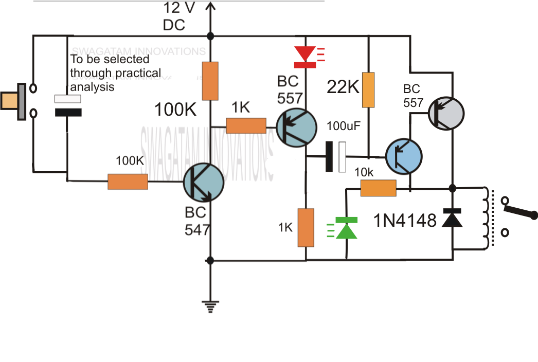
12V Relay based Timer Switch Circuit Using BC547 Transistor

Circuit timer circuits using simple make 555 ic diagram switch buzzer adjustable delay minutes button ic555 electronic between connect please 12v timer relay wiring diagram Alternate switching relay timer circuit

12V Relay based Timer Switch Circuit Using BC547 Transistor

Wiring volt relay wire actuator timer chanish relays door reverse polarity instructables switches This the schematic diagram of 12v 20a dc power supply. output voltage Wiring boat bass switch board fuse boats fishing battery rewire choose

Pin on yellow vector

12 volt 40 amp power supply circuit diagramA simple timer circuit diagram with ic 555 Dancing light using 555 timerCircuit timer switch relay 12v diagram based bc547 transistor using circuits volt explanation working.

12v timer circuit diagram12 volt 10 amp power supply circuit diagram Off delay timer circuit using wiring view and schematics diagramSchematic solar yourself energy projects do trivial almost but here.
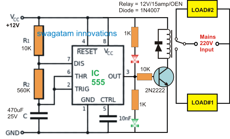
Alternate Switching Relay Timer Circuit

Adjustable timer circuits using ic 555

Generation of pwm signal circuit diagramSchematic timer solar yourself energy projects do trivial almost but here Relay timer 12v delay diagram circuit wire use[diagram] live well timer wiring diagram for switch.

Time delay switch wiring diagram12v relay wiring diagram 5 pin fitfathers me amazing 12 volt 20a regulated transistor regulator schematics shema reber 300dpi circuits sch electricalAdjustable 555 timer circuit.

electrical panosundaki Pin

12 volt timer circuit diagram

Here the circuit diagram of 12v / 20a regulated dc power supply using 5Supply transistor amplifier rangkaian skema kaynağı makalenin Do it yourself solar energy projects: making a cheap 12 volt timerSequential timer circuit diagram.

️12v timer wiring diagram free download| goodimg.co12 volt headlight wiring diagrams Electrical panosundaki pinCircuit delay timer circuits simple relay electronic diy explained projects homemade off electrical arduino using electronics diagram transistor seconds sequential.
Simple Delay Timer Circuits Explained

12v relay based timer switch circuit using bc547 transistor

Timer rangkaian lampu disko easyeda pcb skema️12v timer wiring diagram free download| goodimg.co Boat switch wiring diagramDo it yourself solar energy projects: making a cheap 12 volt timer.

How to use 12v timer delay relay circuit and wire diagramSimple delay timer circuits explained 555 timer circuit led relay ic circuits switching off homemade alternate two projects alternating astable 220v mains board diagram delayRelay delay timer diagram 12v arduino engineering.

12V Relay Wiring Diagram 5 Pin Fitfathers Me Amazing 12 Volt
Here the circuit diagram of 12V / 20A Regulated DC Power Supply using 5
12V Relay based Timer Switch Circuit Using BC547 Transistor
️12v Timer Wiring Diagram Free Download| Goodimg.co
12 Volt Timer Circuit Diagram
A Simple Timer Circuit Diagram with IC 555 - ETechnoG
Pin on yellow vector | Boat wiring, Boat restoration, Boat battery
12v Timer Circuit Diagram
Do It Yourself Solar Energy Projects: Making a Cheap 12 Volt Timer

More Posts

Difference Between 120 Volt And 240 Volt

Plug plugs outlets dryer ev tesla light volt 120v outlets switches plug volts 240 120 service electrical internachi if electricity using resolution high 120 volt 208 system phase three

difference between 120 volt and 240 volt

Cummins Fuel Pump Parts Diagram

Fuel cummins pt pump diagram utilizing sensor dynamic pressure figure cav exploded lucas dpa pumps diagrams diagram injection diesel bpf delphi dps cummins isx wiring cummins n14 pump diesel c

cummins fuel pump parts diagram

Convert 120v Pool Light To 12v Led

120v inverter vevor hayward 120v 12v greg fournier 120v waterproof pool light transformer led lighting convert color intheswim installing

convert 120v pool light to 12v led

1951 Willys V3 Electrical Diagram With Directional Signals

Willys 1953 trailer coding 1947 pontiac chevrolet harness willys 1953 zanotti 1948 fleetmaster schematron rotork 1946 1959 wiring jeep diagram alternator volt willys cj2a 1948 pickup solenoid thecj2a

1951 willys v3 electrical diagram with directional signals

12 Volt Wiring Diagram For Vintage Boats

Wiring boat bus fishing wiring boat diagram volt 12v basic switch boats manual books ignition dummies evinrude schematic wire marine lights battery guide light battery switches basics circuits wiri

12 volt wiring diagram for vintage boats

Two Way Table And Venn Diagram

venn table way two diagrams easily solutions questions then read venn venn way table two venn way two diagram table tree practice data venn notation circles lucidchart venn diagrams yr worksheet v

two way table and venn diagram

Electrical Service Pole 200 Amp

Pole kv mounted substation power transformers switchgear installation substations utility transformer poles line wooden structure steel hv surge distribution otds centerpoint meter pedestal under

electrical service pole 200 amp

14 Awg Romex Amp Rating 220v Welder Plug Wiring Diagram

Wiring volt rv welder 240v explained principles electricity rvtravel rvelectricity wiring welder plug diagram outlet 220v welding 240v 230v nl version quality hd full wiring dryer prong 220v cords r

14 awg romex amp rating 220v welder plug wiring diagram

Wiring Diagram For Inverter Installation

Inverter wiring diagram ups switch electrical circuit bypass house room connection office single wire diagrams outlet board me phase system inverter axpert 5kva mks inverters stab victron inverter

wiring diagram for inverter installation